A view from the factory floor.
In March 1975++, Kerr Glass Manufacturing Company decided to throw open
the doors to their Millville, New Jersey factory, allowing the general public to
enter and witness, firsthand, industrial glassmaking in action. During the open
house, Kerr CD 128 CSC insulators were being made. With camera in hand, my
father - Donald Wentzel - took advantage of this unprecedented opportunity to
photographically document as much of Kerr's insulator making process as was
accessible to public view. His photographs from the basis of this story.
A bit of background information is first required in order to make for better
understanding of the accompanying photos. Kerr's insulator forming
"I-D" machine was of circular design; it held twelve molds. Each of
the twelve mold positions was referred to by station number (1 through 12), with
station 12 being the point at which the insulator was removed from the machine.
My father was able to take pictures of the final three stations (10,11 & 12)
as well as a portion of the initial station (1). He could not film from the side
of the I-D machine where the molds were filled with molten glass, or
"charged". And, although the unphotographed side was where the bulk of
the molding took place, you will see that there were still a number of
interesting processes that occurred after an insulator had been molded into its
intended shape.
The I-D machine was powered by compressed air, with stations
advancing clockwise, rotating on a large geared base. This base is easily
visible in some of the photos. Smaller gears which drove the geared base were
interchangeable to allow altering the speed at which the machine advanced.
Manipulation of machine speed was dictated by three variables: insulator size,
glass temperature and production requirements.
Glass temperature for insulator
production in Millville was in the 1875 degree to 2050-degree range, depending
on the size of the insulator. Smaller insulators could be run hotter, and hotter
glass required the I-D machine to advance more rapidly.
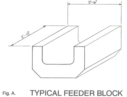
Glass made its way from
the furnace to the I-D machine by flowing through a channel comprised of a
series of "U' shaped refractory material [See Fig. A.]. At the end of this
channel assembly, known as a feeder in glasshouse terminology, molten glass
poured through a circular opening in the bottom of the last feeder block. This opening, called an orifice,
accepted a variety of refractory inserts known as orifice rings. The size of the
opening in the orifice ring determined the diameter of the stream of molten
glass exiting the feeder channel.
After passing through the orifice ring, the
glass stream was cut - or perhaps more accurately, interrupted - at precisely
timed intervals by a scissors-like mechanism. Regulated interruption of glass
flow, or "shearing", produced a piece of molten glass of known mass.
In the instance of a Kerr CSC, the mass required was 17 ounces. After shearing,
the molten mass, descriptively called a "gob", slid under force of
gravity down a polished cast aluminum chute. At the end of the chute, a hinged
deflector funneled the gob into an opening in the top of a waiting mold
assembly.
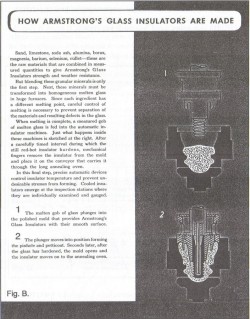
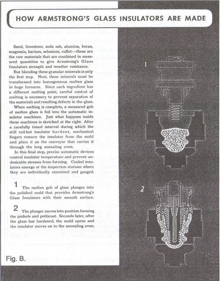
An Armstrong's advertisement reproduced here as Fig. B. serves as a
simple diagram of the molding processes previously described and not shown in
the accompanying photographs. In this advertisement, the dark "T"
shaped item at the very bottom of diagrams 1 and 2 is a stylized representation
of a mold bottom plate (more on that later). A "plunger" assembly is
depicted in a raised position in diagram 1 and as a cutaway view in its lowered
position in diagram 2. This assembly had provisions for forming all the inner
profiles of an insulator, including the threads in the pinhole cavity. Insulator
molding began with the plunger raised completely out of the mold, thereby
creating an opening through which a gob dropped into place.
Medium Image (112 Kb)
Large Image (247 Kb)
In the modem process of insulator molding as employed
by Kerr, it was necessary that the screwpeg, which molded the threads, be
twisted out of an insulator at the same pitch as the threads in order to
preserve the thread profile impressed in the hot glass. In contrast, the much
earlier Pennycuick process of screwpeg retraction relied upon a segmented
screwpeg, which could collapse inward upon itself, and could then be lifted
straight up out of the pinhole.
With that being said, it's time to begin our photographic tour.
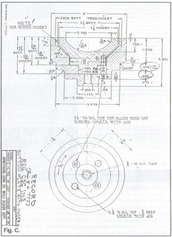
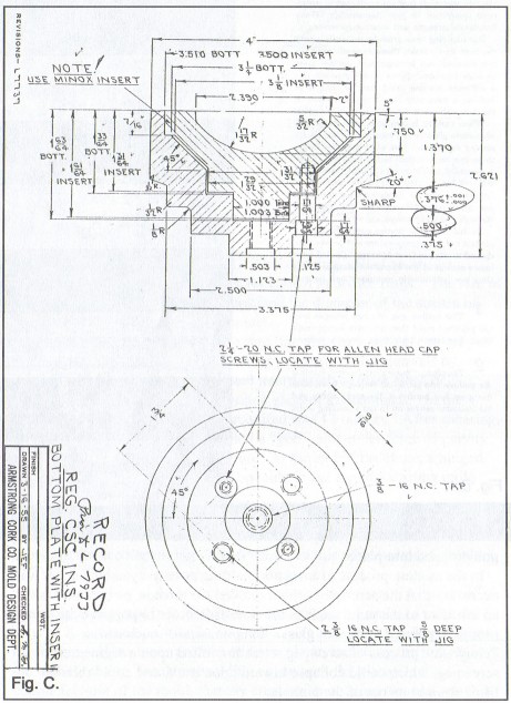
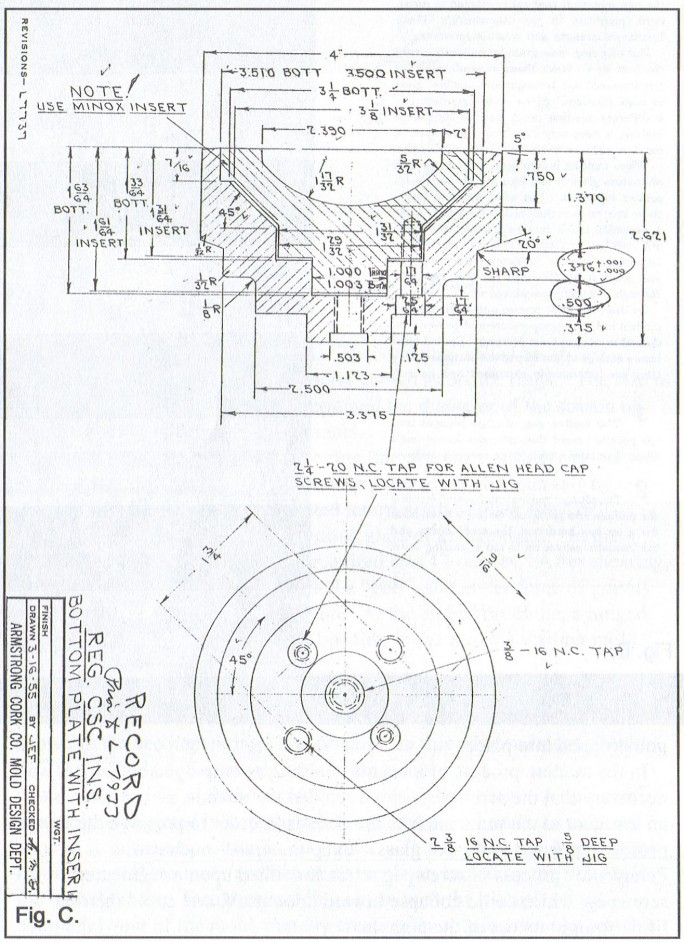
PHOTO #1 is a close-up of the next-to-last machine position, station 11. An
insulator sits upside down, resting only on its mold bottom plate, nearly ready
for removal from the I-D machine. A drawing of a virtually identical Armstrong's
CSC mold bottom plate is included as Fig. C.
Medium Image (86 Kb)
Large Image (179 Kb)
PHOTO #2 is an overview of stations 10, 11 & 12. From left to right:
Station 10 - mold is closed, plunger is fully retracted. Station 11 - Mold
halves have opened. Station 12 - "Take-out" finger (see similar item,
Fig. D.) has captured insulator at its wire groove and is more than halfway into
a 180 degree arcing motion which will place insulator right-side up on a
conveyor leading to the beginning of an annealing lehr. Glass temperature has
cooled to approximately 1100 to 1200 degrees.
Without annealing, a controlled
gradual cooling process, glass products such as insulators would have a tendency
to crack or even shatter due to internal stresses created by temperature
differences between hotter interior and cooler exterior surfaces.
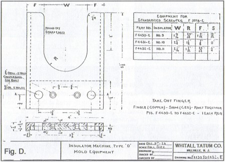
PHOTO # 3 is a close-up view of the transition from station 11 to station.
12. The mold bottom plate with its insulator in place is slowly being pushed
away from the centerline of the mold halves toward the outside edge of the I-D
machine. Note the carrier circuit threads visible on the screwpeg at the top
edge of the photo. A drawing of a virtually identical Armstrong's screwpeg is
shown in Fig. E.

The take-out finger in the foreground of PHOTO #4 has just set
an insulator onto a transfer conveyor. The mold bottom plate in transition from
station 11 to station 12 has advanced about 1/2" closer to the perimeter of
the machine than shown in Photo #3. As the mold assembly rotates toward station
12, the mold bottom plate is extended outward and away from the mold halves until it clears the outermost limits of the mold casing,
thereby enabling removal from the I-D machine by the take-out finger.
The empty
open mold at right in this photo is at station 1. Here, the mold bottom plate
has been drawn completely back into dead center of the mold assembly. Huge
amounts of air are being directed at the empty mold cavity to cool it before the
molding cycle begins anew. The amount of "cooling air" applied to the
mold was adjustable; the machine operator could tweak it for optimum production.
PHOTO # 5, an overview, shows the mold bottom plate fully extended. The take-out
finger (difficult to see in this view - it's angled approx. 45 degrees to the
right) is returning to nestle into the wire groove of an approaching upside down
CSC.
Taken just seconds after the previous picture, PHOTO #6 finds the take-out
finger (angled approx. 80 degrees to the left) nearly in position to secure the
advancing CSC in its specially designed "U" shaped groove.
Generally
speaking, automatic insulator production at Kerr required little or no manual
intervention. It is quite possible that the machine operator in PHOTO #7 is just
showing off for the camera, however, there is something of much greater interest
to note in this picture. Above the operators extended arm can be seen the
brilliant glow of a gob sliding downward toward an awaiting mold.
PHOTO #8 shows
a still incandescent, yellow-hot insulator which has traveled about three feet
toward an annealing lehr after being deposited on a transfer conveyor by the
take-out finger.
KERR INSULATOR PRODUCTION - A view from the factory floor.
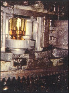
Photo 1. Close up of station 11.
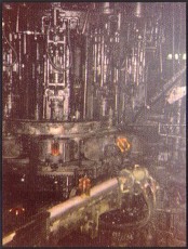
Photo 2. Overview of stations 10, 11 and 12.
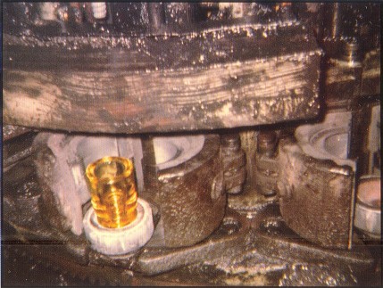
Photo 3. Close up view of the transition from station 11 to station 12.
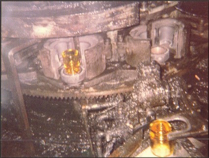
Photo 4. Take-out finger in foreground has just set
an insulator onto a
transfer conveyor.
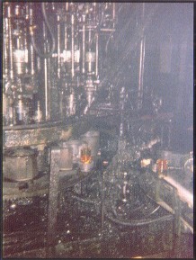
Photo 5. Shows the mold bottom plate fully extended.
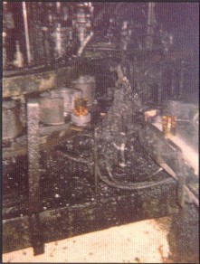
Photo 6. Taken just seconds after Photo 5.,
the take-out finger nearly in
position
to secure advancing insulator.
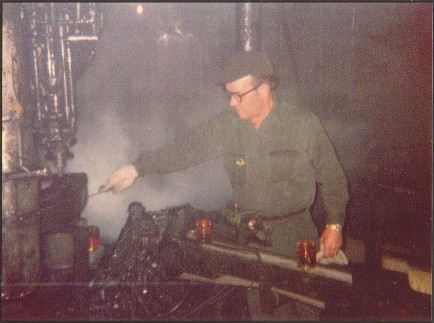
Photo 7. Machine operator.
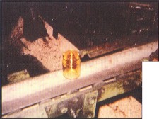
Photo 8. Still incandescent, yellow-hot insulator.
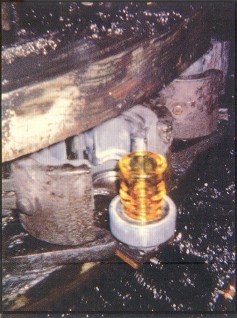
Photo 9. Mold bottom plate, with insulator in
place, is nearing full outward extension.
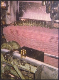
Photo 10. Group of insulators as they approach
the point of transfer to
an annealing lehr conveyor.
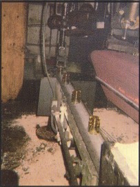
Photo 11. Insulator stopped at end
of the transfer conveyer.
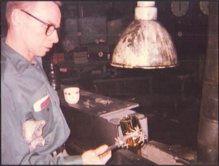
Photo 12. Woven asbestos cloth covers the end of a pair of tongs
used for
visual inspection of hot insulators.
In PHOTO #9, the mold bottom plate, with insulator in place, is nearing full
outward extension. A close comparison of this close-up with the overview in
Photo #5 reveals that the mold bottom plate is about 3/4" short of full
extension. In the right rear of this picture at station 1, an empty mold bottom
plate is in the process of retracting toward its molding position in the center
of the mold halves.
In PHOTO #10, the photographer has turned away from the I-D
machine to film insulators as they approach the point of transfer to an
annealing lehr conveyor. Note the insulator in mid transfer at the top right
comer of the picture.
The insulator stopped at the end of the transfer conveyor
in PHOTO #11 has been grabbed at the wire groove by a swing-arm mechanism in
preparation for lifting to a conveyor that will carry the hot insulators through
an annealing lehr. A careful scan of the floor on either side of the transfer
conveyor reveals the fate of a few unlucky brethren. Eight to twelve hours after
entering the box-like structure of the lehr, the insulators will emerge for
packing, having been cooled to room temperature.
PHOTO #12 Woven asbestos cloth
covers the end of a pair of tongs used for visual inspection of hot insulators.
- - - - - - - - - - - - -
As a fitting finale to this photo-documentary, there is an amusing anecdote
that arose from the 1976 open house.
Kerr management had elected to give away CSC insulators as souvenirs of
the open house tours. One woman, upon being presented her insulator,
graciously handed it back, and asked if she could have one like she had seen
being made. A puzzled plant employee explained that the insulator in his hand
was exactly like those she had just seen. Exactly the same. Identical!
"No, it isn't," the woman insisted, and pointed back toward
the take-out transfer conveyor, still moving a steady stream of incandescent
1100 degree insulators. "I want one of those," she said, adding with
emphasis, "I want one of the yellow ones!"
The truth be told, at the temperatures maintained for glass insulator
production, it was virtually impossible to tell what color the glass would be
when it cooled. All colors look yellow or orange when they're molten. But that
knowledge didn't prevent the old-timers at Kerr from getting a good chuckle over
the woman's comment.


)
)
)
)
)
)
)
)
)
)
)
)
)
)
)